Spinal Seating Modules
Keep the big picture in mind
The wheelchair should be appropriate for the client’s body ‘size’ and ‘shape’ to optimise pressure care, postural alignment, maximise an individual’s functional abilities and comfort. It should enable the client to function in their life roles and in their environment.
Components of a power wheelchair
A typical PWC has a power base, seating system and may have additional equipment essential to the client. The seating system refers to the components of the chair which directly contact and support the client while the power base relates to the components of the chair directly relating to the mobility function. Auxiliary client equipment has a specific function and typically operates independently from the chair, e.g. phone, drinking system and legbag opener.
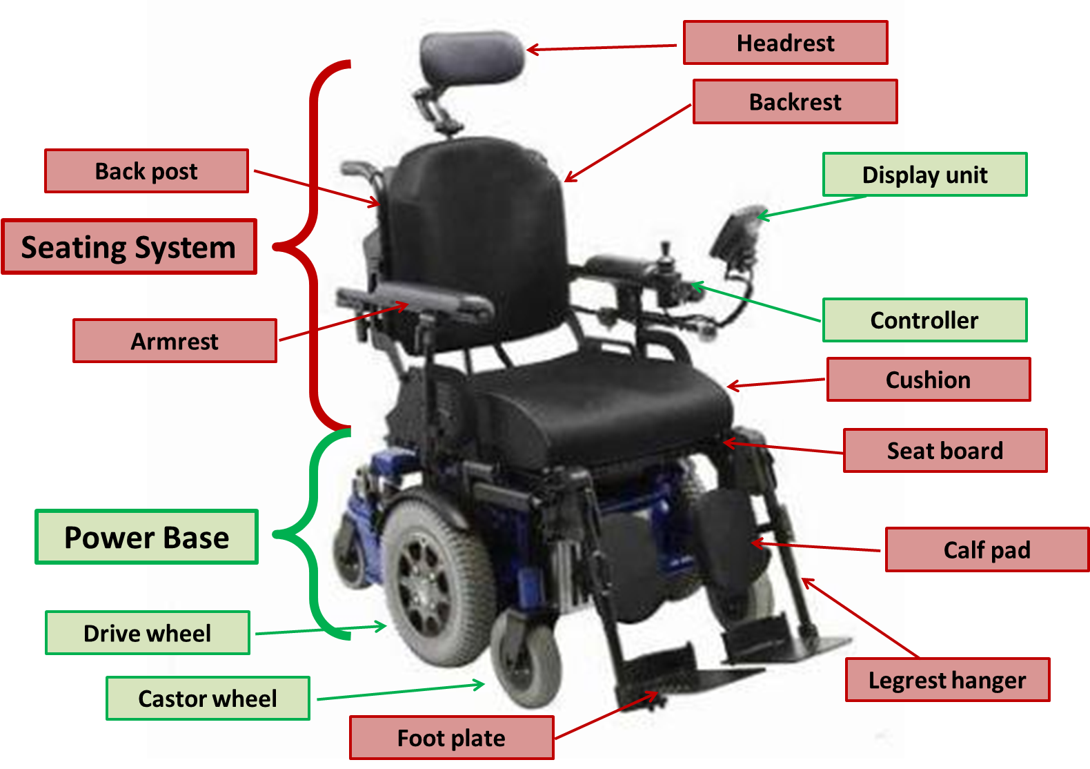
The Power Base
The power base includes the frame, drive system, the wheels and the batteries.
The drive system
The drive system includes the controller (input device), various electronic modules, motors and additional associated software and hardware.
The controller
The controller provides the client or carer the means of driving and steering the wheelchair, as well as providing control of power seating functions such as seat tilt (where fitted). The controller may be:
- Proportional: including most joystick-type controllers and attendant controls. Proportional controllers give smoothly variable speed and direction.
- Non-proportional or digital: including digital switches such as ‘sip and puff’ systems or a head array. Non-proportional controls typically provide directional control but limited capacity to vary speed.
A PWC uses ‘modules’ to control the drive response to user commands with relation to, speed, acceleration, deceleration and tremor dampening, or to provide additional functionality such as infrared or bluetooth connectivity:
- The control module sends inputs from controllers to the motors and power seating mechanisms, provides feedback to user and allows performance adjustment through programming
- The power module directs energy to the motor and to control steering
- A multi-actuator module may be needed for multiple power seating functions
- Specialty control input modules and enhanced display units may be required for specialty control device
- An environmental control module can allow the wheelchair controller to communicate with appliances in the client’s home.
- Other modules have also been developed to provide key functions to the chair, such as the bluetooth module. Modules available vary with PWC manufacturer, and some are available from third party manufacturers.
The PWC’s motors are responsible for driving and steering the chair:
- The motors need to be able to propel the occupied chair in the most challenging terrain (up steep hills) that the client will normally encounter
- A motor’s torque is a measure of its ability to do strong work (like driving uphill) while a motor’s speed is a measure how fast it will drive the chair on flat, smooth terrain. Note that the Australian Government regulates that wheelchairs must not be able to be driven faster than 10km/h.
Many PWCs include an advanced steering system that assist in maintain a straight course on cambered surfaces. Clients with poor hand function, or who use non-proportional control devices such as ‘sip and puff’ or chin control will benefit from a course correction system on sloped pavement and kerb ramps.
Some PWC power bases are fitted with manually operated wheel locks that can be applied to prevent rolling when the chair’s motors are disengaged. Motors for PWCs will also have automatically applied braking systems to prevent uncontrolled rolling when there is no control input.
Drive wheel configuration is named according to the drive wheel location in relation the user’s centre of gravity. The following terminologies on drive wheel are used in Australia. The pros and cons may vary depending on the PWC models and user needs:
FWD - Front wheel drive
- May ‘fishtail’ when driving at speed
- Has better traction on declines than inclines
- Wheelchair turns about the front
- Rear portion of wheelchair swings wide when turning
- No clearance required in front of the chair to turn
- Allows 90 degree thigh to knee angle
- Reversing is not intuitive
RWD - Rear wheel drive
- Good directional stability
- Has better traction on inclines than declines
- Wheelchair turns about the rear (like a car)
- Front portion of wheelchair swings wide when turning
- No clearance required behind chair to turn
- Foot positioning limited by castor swing interference
MWD or CWD - Mid wheel drive or centre wheel drive
- Traction about equal for up and down inclines
- Has four castors for stability (two forwards, to rearwards)
- Intuitive to manoeuvre
- Chair turns about the centre of the power base
- Small footprint and turning radius
- Client may experience a pitching action
- Comparatively rougher ride on uneven terrain
- Allows 90 degree thigh to knee angle
Wheels
Drive wheel and castor size should be selected to suit the environments in which the client will typically be driving.
Drive wheel:
A chair with large diameter drive wheels will climb small lips and ledges more easily and be less affected by crossing cracks in pavement. Wider drive wheels willnot sink as deeply in soft terrain and will have greater traction on loose ground and rough terrain and be less affected by driving along cracks. However, wide tyres can increase chair width which may affect access, and can damage carpet.
Castors:
Castor size and width influence manoeuvrability and kerb climbing. Castor size may also place restrictions upon leg positioning for RWD, MWD and CWD chairs, depending on the swivel diameter of the castors.
Suspension, kerb climbing and stability technologies:
Ongoing design and technology allows the client to have improved ride and control in outdoor terrains.
Stability is particularly important for chin control and mini-joystick users who have difficulty maintaining control on uneven terrain. Where feasible it is good to trial equipment in as many environments as are applicable to the user’s expected use (particularly over rough terrain where this is relevant).
Battery
To maximise battery life, chairs should be put on overnight charge after each day of use and either kept on charge or disconnected if the chair is not to be used for an extended period of time.
- Battery capacity should be adequate for the demands of the user and their environment.
- Sealed or gel cell batteries are required for airline transport and travel. Many airlines will require that batteries be physically disconnected prior to stowage. Note: this feature may not be supplied as standard, and may not be an option, depending on the wheelchair manufacturer. Clients who intend to have their chair transported by air, at any point, should consider airline requirements during prescription.
The Seating System
The ‘Seating System’ includes all of the components of the PWC which directly support the client, such as the cushion, backrest, armrests, legrests, headrest and any additional postural supports which are mounted to the chair. These components are introduced in Module 7 and Module 8. Unlike the power base, there is often significant scope for the use of third party seating componentsto best achieve the clinical objectives of seating. The selection of seating components should be based on a thoroughassessment of posture and pressure as described in Module 7 and Module 8. Seating systems in PWCs typically have scope for adjustment of the seat width and depth and other basic seating dimensions.
The seating system may also incorporate power seating functions to provide client and carers with additional capacity to control posture, manage pressure and enhance function. When using power seating functions it is important to ensure that the client can control the seat functions throughout the range of body position and is able to return to the initial posture after using power seating functions.
Example
A client with reduced upper arm function who drives with a manual joystick may not be able to overcome gravity when in tilt to return the chair to level, in this case limits can be placed on the degree of tilt that the chair is able to achieve.
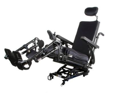
It is prudent to keep the system as simple as possible, without compromising the high priority seating and wheeled mobility goals. Increased complexity in the system increases the need for client and carer training, and also increases operational complexity, equipment maintenance and future repairs. Compromises must be discussed case by case with the client during the process of prescription.Possible power seating functions include tilt-in-space, seat elevation, backrest recline and legrest elevation. Some PWCs also use a combination of power seating functions to effectively stand the client upright.
Tilt-in-space: the seat angle rotates around a pivot point to raise or lower the front of the seat without changing the seat-to-back angle. Tilt-in-space typically allows seating angles from -5° (front of the seat a little lower than the rear) to 65° (backward).
- ‘Weight-shift tilt’ moves the seat on the power base during tilting so that the balance of the chair as a whole remains unaltered, whereas a ‘fixed pivot’ tilt-in-space seating function requires a longer wheel base to maintain stability
- Tilt-in-spacecan be an effective strategy for pressure management. See Module 8.
- A tilt-in-space system uses gravity to improve posture, field of vision, pelvic stability and body positioning. See Module 7.
- A small degree of tilt-in-space adjustment can allow the user to optimise balance and stability in activities such as negotiating kerb ramps and steep descents.
- Tilt-in-space improves access to outdoor terrain and entry to vehicles by allowing adjustment of the ground-to-foot support clearance.
Seat elevation: the seating system can be lowered or raised relative to the floor height to improve transfer, functional reach and social interaction.
- Most chairs with seat elevation will have their forward speed limited when the seat is elevated
- Wheelchair manufacturers are aware that increases in seat elevation reduces chair stability and have taken measures to manage this risk.
- Power backrest recline: The power recline system changes the seat-to-back support angle. Ensure that the client has the muscle length and joint flexibility to assume these changes in angle,
- The basic power recline pivots the backrest on the seat which can cause some sliding of the backrest against the body during recline, because the pivot of the backrest is not aligned with the hip joints. Anti-shear recline systems are designed to minimise this sliding movement
- Power tilt can be used with power recline to enhance pressure and posture management
- When using a combination of seat tilt and backrest recline it is important for the client to correctly sequence these operations to avoid being pushed forward on the seat, as follows:
- When going back: tilt first, then recline backrest.
- When regaining an upright position: backrest up and then un-tilt.
Legrest elevation:
The legrest elevation system changes the seat to leg rest angle. It is important that the client has the muscle length and joint flexibility to assume these changes in angle, in this case the sequencing for power functions is as follows:
- When going back: tilt first, then recline backrest, then elevate legs.
- When regaining an upright position: legrests down, backrest up, and then un-tilt.
The legrest elevation mechanism should ideally pivot as close as possible to the axis of the knee joints to reduce displacement that will cause shear or raise the knees compromising pressure management. Anti-shear legrest elevation systems are designed to move the foot supports with the body to avoid these undesirable outcomes. Ensure that legrest elevation system include sufficient calf support for the extended position.
Power seating functions working together:
When multiple power seating functions are to be used together it is recommended that they are assessed and prescribed together with a customised or synchronised power seating program (one input controlling several seating functions).
The possible applications include:
- Improved pressure management
- A change in posture for rest, or enhanced functional activities such as self-catheterisation
- Reduced need for attendant care
- Management of orthostatic hypotension
- Pain management
- Oedema management- elevating the legs above the heart
- Improvement to breathing capacity.
References
- Denison I, Gayton D. Power wheelchairs: a new definition. [Internet]. Assistive Technology & Seating Service Vancouver Coastal Health; 2006 [cited Oct 2015]. Available from: http://www.assistive-technology.ca/studies/scin.pdf.
- Rehabilitation Engineering & Assistive Technology Society of North America (RESNA). RESNA position on the application of tilt, recline and elevating legrests for wheelchairs. [Internet]. RESNA; 2008 [cited Oct 2015]. Available from: http://www.rstce.pitt.edu/RSTCE_Resources/Resna_Position_on_Tilt_Recline_Elevat_Legrest.pdf
- Queensland Spinal Cord Injury Service. Powerdrive wheelchair features. [Internet]. Queensland Spinal Cord Injury Service: 2015 [cited Oct 2015]. Available from: https://www.health.qld.gov.au/qscis/documents/pdwc-features.pdf